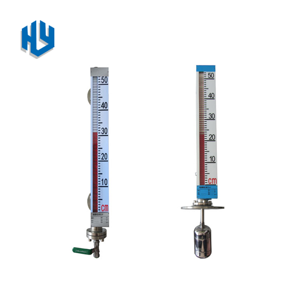


The flip-column magnetic float level gauge uses a float as the measuring element and a magnet-driven flip-column display. It does not require energy. It is suitable for various environments such as low temperature to high temperature, vacuum to high pressure. It is an ideal level for petroleum, chemical and other industrial sectors.
CONTACT USThe magnetic float level gauge is equipped with upper and lower limit switch outputs, which can
achieve remote alarm and limit control.The magnetic float level gauge is equipped with transmitter,
which can achieve the remote indication, detection and control of the liquid level. According to the
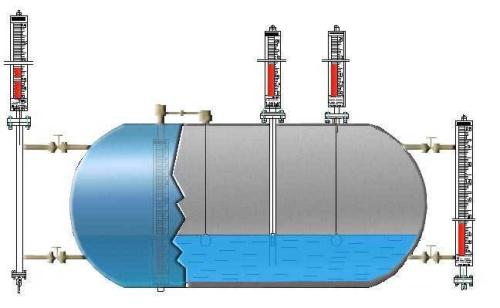
different installation positions of the containers, there are two types of side mounting and top mounting
methods. According to different working media, four materials are provided: stainless steel, stainless
steel lined with PTFE, ABS plastics and PP-R, PVC, of which ABS, PP-R, PVC, stainless steel lined
with PTFE are suitable for acid, alkali and other corrosive medium.

Structure and working principle
1. Basic type
According to the principle of buoyancy, the float moves up and down with the rise and fall of the liquid level
in the measuring tube. The permanent magnet in the float drives the red and white turning columns to turn
over 180° through magnetic coupling. The column turns from white to red, and turns from red to white as it
descends, thus realizing the indication of the liquid level.
2. Upper and lower limit switch output
Install the controller at the upper and lower limit positions set by the user on the main tube of the level gauge.
The controller has a reed switch with self-holding function or an alarm switch without memory function
according to user requirements. The movement of the liquid level causes the reed switch to act to realize alarm
or limit control.
3. Remote type
Install a transmitter on the float level gauge. The transmitter is composed of a measuring unit and a transmitting
unit. It moves up and down through the magnetic float, and through magnetic coupling, the measuring elements
in the guide rod act in sequence to obtain the resistance signal change. Converted into 0~10mA or 4~20mA
standard current signal output, connected with digital display instrument or computer to achieve remote
transmission purpose.
4. Steam jacket type
The measuring cylinder is equipped with a steam heating layer to maintain the temperature of the measured
medium in the measuring cylinder and prevent the measured medium from freezing and freezing due to
changes in the ambient temperature.
5. Electric heating type
An electric heating layer is added to the measuring cylinder, and an electric heating device is built in. The
heating device transfers heat evenly to the measuring cylinder through the heat transfer oil, which plays a
role of heating and keeping warm.
Installation | Side Mounting | Top Mounting | ||
Range | 200~30000mm | 200~6000mm | ||
Process pressure | 0.6,1.6,2.5,4.0Mpa, 10Mpa to 35MPa | 0.6 ,1.6 ,2.5Mpa, 4.0MPa | ||
Density | >0.5g/cm3 | 0.76g/cm3 | ||
Flange | SS | DN20-40(DN20PN4.0)
| DN200-25(DN200PN2.5)
| |
ABS | DN20-10(DN20PN1.0) (GB9119—88) | DN200-6 (DN200PN0.6)
| ||
Measuring tube | 1Cr18Ni9Ti、ABS、PP-R、PVC、SS with PTFE inner linning | |||
Medium Temperature | SS :-40~450℃、PPR: 120℃、ABS:70℃、
| |||
Ambient temperature | -40~+450℃ | |||
Accuracy | ±10mm | |||
Viscosity | ≤1st(10-4m2/s) | |||
Switch output
| 1、Sensitivity:10mm 2、Contact capacity:AC220V 2A 3、Contact life:5×10⁴次 4、Explore proof:iaIICT4 | |||
Remote output | 1、Accuracy:±1.5% 2、Output load:750Ω 3、Signal output:0-20mA,220V AC 4-20mA,24V DC 2 Wire 4、Explore proof:iaIICT4 | |||
Order Selection
| UHZ | Magnetic Float Level Gauge | |||||||||
| Installation | S | | Side Mounted | |||||||
| T | Top Mounted | |||||||||
Construction | 1 | Basic type | ||||||||
| 2 | Switch Alarm type | |||||||||
| 3 | Remote output type | |||||||||
| 4 | Jacket type | |||||||||
| 5 | Electric heating type | |||||||||
Temperature | L | 0~120oC | ||||||||
| M | 0~180oC | |||||||||
| H | 0~300oC | |||||||||
| S | 0~450oC | |||||||||
Pressure | 1 | 0~1.6Mpa | ||||||||
| 2 | 0~2.5Mpa | |||||||||
| 4 | 0~4.0Mpa | |||||||||
| 6 | 0~6.3Mpa | |||||||||
| 10 | 0~10Mpa or more | |||||||||
Process Connection | F | Flange | ||||||||
| C | Tri-clamp | |||||||||
| T | Thread | |||||||||
Material of measuring tube | S4 | | | | SS304 | |||||
| S6 | SS306 | |||||||||
| P | PPR/PVC | |||||||||
| L | | | | SS with Linning | ||||||
| Range(center distance bt 2 flanges) | 200~30000mm | |||||||||
| Other request | Pls offer | |||||||||
Previous: No more
Next: No more
