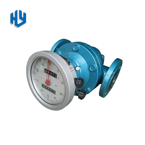

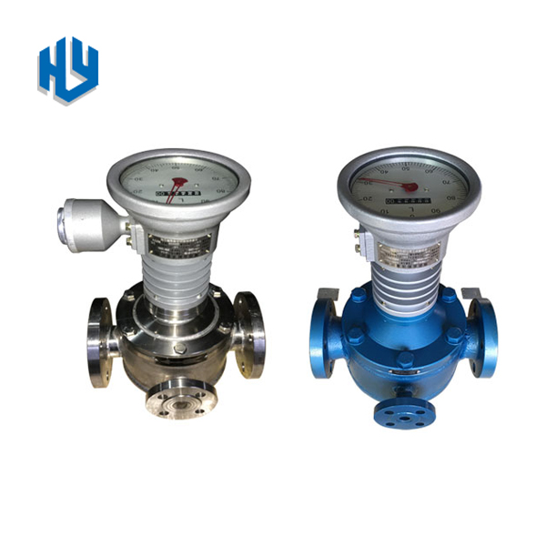

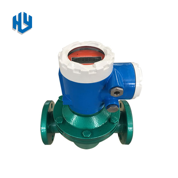

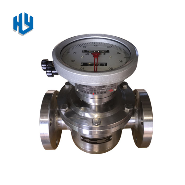


Oval gear flowmeter is a volumetric meter for continuous or intermittent measurement and control
of liquid flow in a pipeline. It has many advantages, such as large range, high accuracy, small pressure
loss, strong viscosity adaptability, measurement of high temperature and high viscosity liquid, convenient
calibration, installation suggestion and so on. It is suitable for flow measurement in petroleum, chemical,
chemical fiber, transportation, commerce, food, medicine and health departments.
Structure and Working Principles
Oval gear flowmeter consists of flow transmitter and counting mechanism. A high temperature
flowmeter if formed if a radiator is installed between the transmitter and the counting mechanism.
The transmitter consists of a metering chamber and a sealing coupling with a pair of elliptical
gear rotors. The counting mechanism comprises a deceleration mechanism, a regulating mechanism, a
counter and a transmitter.
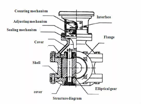
Counting mechanism Number of interfaces of transmitter Regulating mechanism Sealing coupling Top cover
Flange Cover plate Shell Bottom cover Oval gear
The metering chamber has a crescent cavity composed by a pair of oval gear and cover plate as the metering
unit of flow. The oval gear is rotated by the pressure difference between the inlet and outlet of the
flowmeter so that the liquid is continuously measured by the crescent cavity and sent to the outlet.
The liquid that flows every turn is four times of the crescent cavity. By sealing coupling, the total
number of turns of oval gear and the speed of rotation are sent to the counting mechanism or transmitter.
Thus, we can know the total amount of liquid and instantaneous flow through the pipeline.
Type of Transmitter
Counter Function | A1 | A | Z | 13 | J1 | ELZ |
Pointer Cumulative six rollers | ● | ● | ||||
Pointer Cumulative six rollers Reset | ● | ● | ● | |||
Pointer With message | ● | ● | ||||
Single message (signal output) | ● | |||||
LCD display (Instantaneous, cumulative, 4—20mA, pulse, RS485) |
● |
Model and Material of Main Parts
Item | Cast Iron type | Cast steel type | High-tem cast iron type | High-tem cast steel type | High- viscositycast iron type | High- viscosity cast steel type | Stainless steel |
Customerized |
Model |
LC—A |
LC—E |
LC—TA |
LC—TE |
LC—NA |
LC—NE |
LC—B |
LC—13 |
Body |
Cast iron |
Cast steel |
Cast iron |
Cast steel |
Cast iron |
Cast steel |
SS |
Various materials |
Gear | Cast Iron | Cast Iron | Cast iron | Cast iron | Cast iron | Cast iron
| SS | Various materials |
Technical Features
1.Normal Type
LC-A |
LC-B |
LC-E | ||
Nominal pressure MPa |
1.6 |
1.6, 2.5, 4.0, 6.3 |
1.6, 2.5, 4.0, 6.3 | |
Temperature range ℃ | Pointer indicator type: -20~+80;High-temperature pointer type: -20~+200; LCD type: -20~+60;High-temperature LCD type: -20~+150; | |||
Precision level | 0.5% | |||
OD (mm) | Viscosity: 0.6—2mPa.s | Viscosity: 2—200mPa.s | ||
10 | 0.2-0.4 m3/h | 0.08—0.4 m3/h | ||
15 | 0.6-1.5 m3/h | 0.3—1.5 m3/h | ||
20 | 0.8—3 m3/h | 0.6—3 m3/h | ||
25 | 1.2—6 m3/h | 0.8—6 m3/h | ||
40 | 5—15 m3/h | 3—15 m3/h | ||
50 | 6—24 m3/h | 4—24 m3/h | ||
65 | 10—40 m3/h | 8—40 m3/h | ||
80 (light type) | 10—40 m3/h | 8—40 m3/h | ||
80 (heavy type) | 15—60 m3/h | 10—60 m3/h | ||
100 | 30—100 m3/h | 15—100 m3/h | ||
150 | 45—190 m3/h | 34—190 m3/h | ||
200 | 68—340 m3/h | 56—340 m3/h | ||
2.High Viscosity Type
LC-NA | LC-NE | LC-NB | ||
NominalpressureMPa | 1.6 | 1.6、2.5、4.0、6.3 | 1.6、2.5、4.0、6.3 | |
Temperature range ℃ | Pointer indicator type: -20~+80;High-temperature pointer type: -20~+200; LCD type: -20~+60;High-temperature LCD type: -20~+150; | |||
Precision level | 0.5% | |||
Flow range m3/h | ||||
OD(mm) | Viscosity: 200—1000mPa.s | Viscosity: 1000-2000mPa.s | ||
10 | 0.04—0.3 m3/h | 0.03-0.2 m3/h | ||
15 | 0.2—1.0 m3/h | 0.1-0.7 m3/h | ||
20 | 0.4—2.1 m3/h | 0.25-1.5 m3/h | ||
25 | 0.6-4.2 m3/h | 0.6-3 m3/h | ||
40 | 2.1—10.5 m3/h | 1.0-7.5 m3/h | ||
50 | 2.4-16.8 m3/h | 2-12 m3/h | ||
65 | 6-28 m3/h | 4-20 m3/h | ||
80 (light type) | 6-28 m3/h | 4-20 m3/h | ||
80 (heavy type) | 8-42 m3/h | 6-30 m3/h | ||
100 | 10-70 m3/h | 10-50 m3/h | ||
150 | 27-133 m3/h | 19-95 m3/h | ||
200 | 48-238 m3/h | 34-170 m3/h | ||
Dimensions
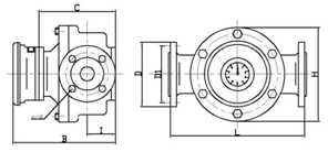
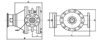
DN10-DN50(light type) DN50-DN100
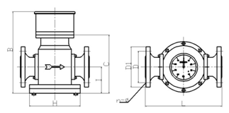
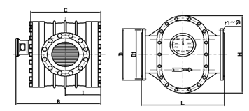
DN65/DN80(light type) DN150-DN200
1.LC-A, LC-NA
DN(mm) | L(mm) | H(mm) | B(mm) | C(mm) | I(mm) | D(mm) | D1(mm) | N | Ф(mm) |
10 | 150 | 100 | 210 | 120 | 45 | 90 | 60 | 4 | 14 |
15 | 170 | 118 | 226 | 136 | 48 | 95 | 65 | 4 | 14 |
20 | 200 | 150 | 238 | 148 | 53 | 105 | 75 | 4 | 14 |
25 | 260 | 180 | 246 | 156 | 60 | 115 | 85 | 4 | 14 |
40 | 245 | 180 | 271 | 181 | 77 | 145 | 110 | 4 | 18 |
50 (light type) |
290 |
218 |
310 |
220 |
80 |
160 |
125 |
4 |
18 |
50 (heavy type) |
340 |
250 |
372 |
230 |
88 |
160 |
125 |
4 |
18 |
65 | 325 | 245 | 320 | 220 | 90 | 180 | 145 | 4 | 18 |
80 (light type) |
325 |
245 |
320 |
220 |
90 |
195 |
160 |
8 |
18 |
80 (heavy type) |
420 |
325 |
433 |
253 |
118 |
195 |
160 |
8 |
18 |
100 | 515 | 418 | 458 | 278 | 131 | 215 | 180 | 8 | 18 |
150 | 540 | 515 | 557 | 377 | 210 | 280 | 240 | 8 | 23 |
200 | 650 | 650 | 624 | 444 | 247 | 335 | 295 | 12 | 23 |
2.LC-E,LC-NE
DN(mm) | L(mm) | H(mm) | B(mm) | C(mm) | I(mm) | D(mm) | D1(mm) | N | Ф(mm) |
10 | 150 | 100 | 212 | 120 | 45 | 90 | 60 | 4 | 14 |
15 | 200 | 138 | 232 | 142 | 53 | 95 | 65 | 4 | 14 |
20 | 250 | 164 | 250 | 150 | 63 | 105 | 75 | 4 | 14 |
25 | 300 | 202 | 252 | 162 | 68 | 115 | 85 | 4 | 14 |
40 | 300 | 202 | 293 | 203 | 83 | 150 | 110 | 4 | 18 |
50 (light type) | 320 | 220 | 325 | 235 | 85 | 160 | 125 | 4 | 18 |
50 (heavy type) | 384 | 262 | 394 | 394 | 88 | 160 | 125 | 4 | 18 |
65 | 350 | 260 | 365 | 275 | 100 | 180 | 145 | 4 | 18 |
80 (light type) | 350 | 260 | 365 | 275 | 100 | 200 | 160 | 8 | 18 |
80 (heavy type) | 450 | 337 | 452 | 272 | 118 | 200 | 160 | 8 | 18 |
100 | 555 | 442 | 478 | 298 | 131 | 220 | 180 | 8 | 18 |
150 | 540 | 510 | 557 | 377 | 210 | 285 | 240 | 8 | 23 |
200 | 650 | 650 | 624 | 436 | 247 | 340 | 295 | 12 | 23 |
3.LC-B, LC-NB
DN(mm) |
L(mm) |
H(mm) |
B(mm) |
C(mm) |
I(mm) |
D(mm) | D1(mm) |
N |
Ф(mm) |
10 | 150 | 100 | 212 | 120 | 45 | 90 | 60 | 4 | 14 |
15 | 200 | 120 | 226 | 132 | 48 | 95 | 65 | 4 | 14 |
20 | 230 | 150 | 238 | 148 | 58 | 105 | 75 | 4 | 14 |
25 | 260 | 180 | 246 | 156 | 64 | 115 | 85 | 4 | 14 |
40 | 265 | 180 | 271 | 181 | 77 | 150 | 110 | 4 | 18 |
50 | 265 | 180 | 290 | 200 | 92 | 160 | 125 | 4 | 18 |
65 | 365 | 260 | 400 | 310 | 125 | 180 | 145 | 4 | 18 |
80 (light type) | 350 | 260 | 365 | 275 | 125 | 200 | 160 | 8 | 18 |
80 (heavy type) | 420 | 325 | 443 | 263 | 118 | 200 | 160 | 8 | 18 |
100 | 515 | 418 | 468 | 288 | 131 | 220 | 180 | 8 | 18 |
Order Selection
LC | — | Oval gear flowmeter | |||||||
T | High temperature type | ||||||||
U | Jacket type | ||||||||
N | High viscosity type | ||||||||
A | Cast Iron type | ||||||||
E | Cast steel type | ||||||||
B | SS304 | ||||||||
C | SS316 | ||||||||
DNXXX | DN010~DN200 | ||||||||
.1 | Nominal pressure (1.0Mpa) | ||||||||
.2 | Nominal pressure (1.6Mpa) | ||||||||
.3 | Nominal pressure (2.5MPa) | ||||||||
.4 | Nominal pressure (4.0MPa) | ||||||||
.6 | Nominal pressure (6.3MPa) | ||||||||
A/A1 | A:mechanical pointer indicator; A1 can be equipped with transmitter | ||||||||
A5/A6 | A5:Zero reset pointer indicator, A6 can be equipped with transmiter transmitter | ||||||||
Z | Double-handle reset | ||||||||
13 | Output signal only (pulse, 4-20mA) | ||||||||
ELZ
| LCD dispaly 1. 4-20mA 2. Puse 3. RS485
| ||||||||
Previous: No more
Next: No more
